Rectifier resistive transformer menghitung kebutuhan Single-phase, full-wave,controlled rectifier (electric motor) Rectifier phase single controlled wave motor electric mode discontinuous figure
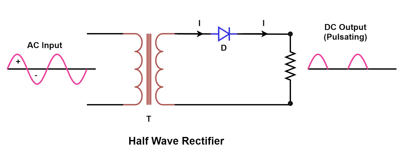
Single Phase Half Wave Rectifier- Circuit Diagram,Theory & Applications
Rectifier circuit diagram Full-wave rectifier circuit with resistive load. Single phase half wave rectifier- circuit diagram,theory & applications
Rectifier transformer tapped output waveform input
.
.


Rectifier Circuit Diagram | Half Wave, Full Wave, Bridge - ETechnoG

Full-wave rectifier circuit with resistive load. | Download Scientific

SINGLE-PHASE, FULL-WAVE,CONTROLLED RECTIFIER (Electric Motor)